Monday, June 27, 2011

Creating an AutoCAD ribbon component

It might always seem that everyone is using the most recent version of AutoCAD, this is not necessarily true though. I work for a global consulting engineering firm and we have been on AutoCAD 2008 up until just earlier this year. The same goes for several of our clients and it is not uncommon for us to deliver packages in pre-AutoCAD 2008 environments.

This sounds archaic and out-dated but the real world has many variables that come into play and it is not feasible to always upgrade as soon as a new version of AutoCAD is released. Sure, if your company is working strictly with Autodesk products upgrades can be smooth and more timely, but when you rely on several different AutoCAD vertical packages and customized environments upgrades can become a time consuming effort that requires planning and strategy.

Regardless of what version of AutoCAD you may be working with I thought it might be helpful to do a post on User Interface (UI) and specifically talk about converting a pre-AutoCAD 2009 toolbar button to an AutoCAD 2011 ribbon component.

Let's say you have a custom toolbar in AutoCAD 2008 with a button that executes a command defined in mnl or dll that inserts a valve on a specific layer, breaks a line, allows rotation, etc. You want the same functionality in AutoCAD 2011 but you would like for your users to be able to execute the command from a custom ribbon. The command behind the button will not change, it can still execute with the same definition (unless it is in .net and the dll needs to be recompiled using the updated api files) we just need to make the command available via the ribbon.

To get started: Copy your custom content (cui, mnl, etc) to a new folder. Open AutoCAD 2011 and create a new user profile (Options | Profiles | Add To List)


To migrate a legacy cui file type in cui or select cui, User Interface from the Manage tab on the AutoCAD 2011 ribbon. From the Customize User Interface dialog click the Transfer tab. On the right side of the transfer tab (Customizations in New File) click Open. Note: to see .cui files (which are legacy since they are not .cuix) you will need to select .cui in the file type dropdown list.


Browse to the new folder created above and open the cui file. As soon as the cui file is open click the save icon and a new cuix file is created.


You can now choose how the architecture of your new profile will be built, I will partially load the new cuix file in to my main AutoCAD cui file. Later, we can come back and load it as the enterprise cui but while we are developing it we need to be able to write to it.

Just by partially loading the cuix file you will have the functionality that was in the legacy cui environment. This is all that is required to transfer functionality of a legacy menu system into a newer version of AutoCAD. Now let's create a new ribbon tab instead of offering only toolbars.

A quick note on the architecture of the ribbon. There is one ribbon with multiple tabs (these are the different areas that are selected at the top of the ribbon) each tab is divided into panels. We will create 1 new tab with a panel that contains our valve command. There is quite a bit more detail that can happen at the panel level such as sub-panels, panel rows, dropdowns, and separators but we will just focus on the ribbon tab and a single panel in this post.

Open the cui, scroll down to Partial Customization Files and select our custom cui file. Click the Ribbon node, right click on Tabs and select New Tab.


The ribbon tab is a container that will contain a panel or multiple panels. Create a new panel.


Populating a panel with commands that are already defined is simply a matter of dragging the command from the cui command list up to the panel.


To associate the panel with a tab drag the panel up into the tab


This association only needs to be created once. As the commands within the panel are changed (added or removed) they will reflect on the tab.

In order for the new ribbon tab to be available it needs to be toggled to display for the current workspace (similar to other toolbars, menus, and ribbon tabs).


The new ribbon tab now shows up in the main AutoCAD ribbon


And when it is selected the new panel (or panels) display with the commands that were added to each panel (Note, the order of the commands on the panel is controlled back in the cui by dragging the commands to their desired row and order).

When the new panel component is selected the same command is invoked! You have streamlined the migration of a legacy toolbar button to a new sexy ribbon component. Depending on how your new Ribbon/Tab/Panel layout ends up you may want to take the time to create new graphics for the components and if you choose to do so it is just a matter of pointing to the new image file from the ribbon element.


Wednesday, January 26, 2011

Manage custom files in multiple offices

Our streamlined environment now contains custom files, apps (dll and lisp), and other content we want our users to have available in their AutoCAD environment. We have explored some streamlined methods for maintaining this content in a central network location and getting the content to the users with minimal effort - basically a single desktop icon that points to our profile file (.arg).

In this post we will talk about extending this streamlined environment to multiple offices and still only maintaining one set of custom AutoCAD files. That last statement sounds contradictory but using an available Microsoft utility called Robocopy it is very possible and even easy.

Let's first look at the network structure for a multiple office environment. Let's say we have 3 offices (O1, O2, O3) each with its own server (S1, S2, S3), we want to first identify where our custom content will be stored on each server.

Office 1
\\S1\SLD\2010

Office 2
\\S2\SLD\2010

Office 3
\\S3\SLD\2010

Pick a drive letter that can be used consistently in each office (we will use S:\\) and depending on which office a user will be working in the drive letter should be mapped to the server for that office.

An easy way to manage drive mappings is to use a batch file that can be ran directly from a hyperlink on a web based tool such as Microsoft SharePoint.

Here is the code for the batch file to map a network drive:


REM batch file to map S:\ drive to \\S1\SLD\
@ECHO OFF
CLS
REM this line of code will disconnect S:\ if it is already mapped
NET USE S: /delete
NET USE S: \\S1\SLD\
echo S:\ mapped successfully!
PAUSE
ECHO ON

I did not add any error checking in this code but nonetheless this batch file can now be executed directly or by hyperlinking to it and the users' drives will be mapped to the correct location.

Now, each user at each office has the S:\ mapped and it points to the SLD folder which is on that office's local file server. If Office 1 is the master office that is where you will maintain the custom AutoCAD content. Any changes, additions, or deletions will be made on S1 (Office 1 server). We can use Robocopy to copy the content on S1 to S2 and S3. The Robocopy script can be executed on scheduled intervals so you can be assured that your master content on S1 is replicated on S2 and S3 as frequently as needed. The Robocopy script will be a batch (.bat) file. It can be created in a standard text editor and when ready should reside on a server with the Robocopy utility on it.

Here is the code to Robocopy a folder that contains custom files to each of the servers.


REM replicate CAD content to multiple offices
CLS
SET DATESTAMP=%date:~10,4%-%date:~4,2%-%date:~7,2%
REM Use variables to manage offices and servers
SET SOURCESITE=OFFICE1
SET SOURCESERVER=S1
SET TARGETSITE1=OFFICE2
SET TARGETSERVER1=S2
SET TARGETSITE2=OFFICE3
SET TARGETSERVER2=S3
REM Create folders for log files
IF NOT EXIST
 "\\%SOURCESERVER%\SLD\2010\replications\logs"
MKDIR
 "\\%SOURCESERVER%\SLD\2010\replications\logs"
REM Replicate CAD content
ROBOCOPY "\\%SOURCESERVER%\SLD\2010\Custom" "\\%TARGETSERVER1%\SLD\2010\Custom" /xf "*.bak" /eta /r:1 /w:15 /z /MIR /LOG:"\\%SOURCESERVER%\SLD\2010\replications\logs\%DATESTAMP%-%SOURCESERVER%_to_%TARGETSERVER1%-%TARGETSITE1%.log" /np /tee
ROBOCOPY "\\%SOURCESERVER%\SLD\2010\Custom" "\\%TARGETSERVER2%\SLD\2010\Custom" /xf "*.bak" /eta /r:1 /w:15 /z /MIR /LOG:"\\%SOURCESERVER%\SLD\2010\replications\logs\%DATESTAMP%-%SOURCESERVER%_to_%TARGETSERVER2%-%TARGETSITE2%.log" /np /tee
REM Generate Log File
ECHO DateStamp=%DATESTAMP% >  "\\%SOURCESERVER%\SLD\2010\replications\logs\%DATESTAMP%_Information.log"
ECHO SourceSite=%SOURCESITE% >> "\\%SOURCESERVER%\SLD\2010\replications\logs\%DATESTAMP%_Information.log"
ECHO SourceServer=%SOURCESERVER% >> "\\%SOURCESERVER%\SLD\2010\replications\logs\%DATESTAMP%_Information.log"
ECHO TARGETSITE1=%TARGETSITE1% >> "\\%SOURCESERVER%\SLD\2010\replications\logs\%DATESTAMP%_Information.log"
ECHO TARGETSERVER1=%TARGETSERVER1% >> "\\%SOURCESERVER%\SLD\2010\replications\logs\%DATESTAMP%_Information.log"
ECHO TARGETSITE2= %TARGETSITE2% >> "\\%SOURCESERVER%\SLD\2010\replications\logs\%DATESTAMP%_Information.log"
ECHO TARGETSERVER2 =%TARGETSERVER2% >> "\\%SOURCESERVER%\SLD\2010\replications\logs\%DATESTAMP%_Information.log" 
SET DATESTAMP=
SET SOURCESITE=
SET SOURCESERVER=
SET TARGETSITE1=
SET TARGETSERVER1=
SET TARGETSITE2=
SET TARGETSERVER2=
PAUSE


You will notice there are quite a few parameters in the Robocopy command. This script will also generate log files which are handy to make sure the Robocopy is happening.

The key concepts in this post are having a common location in each office, a way for users to easily manage their drive mappings, and the same content at all locations all the time.

The way the Robocopy presented in this post will work is any changes, additions, or deletions to files in the master location will also take place in the target locations when the robocopy script is executed.

The Robocopy script is saved as a batch (.bat) file. You can then set this to run at a desired interval using Windows Task Scheduler.

This opens up a whole new realm of streamlining a design environment as we can now manage custom AutoCAD content in one location but share it with multiple locations.

Thursday, December 16, 2010

Architecture of a Streamlined Design Environment

As I have mentioned in previous posts I am a fan of using the mnl as an access point to all custom AutoCAD menu content. Another popular method (which I avoid) is to place menu loading calls in the acaddoc.lsp file. My philosophy is to minimize modifying out of the box AutoCAD files and keeping as much custom content separated from delivered AutoCAD files as possible. This helps for a few reasons: one, upgrades are easier and smoother if all of your custom content is separate from the delivered AutoCAD files and can simply be reintroduced to the next version of AutoCAD. Another benefit is setting up a machine for a user is quick and easy and can be done by IT support in many cases (since out of the box AutoCAD is all that is needed and custom content can be introduced simply by adding a desktop shortcut that points to an arg file). Thirdly, this method keeps your menu sets organized so if you have multiple menu sets and AutoCAD user profiles they won't be conflicting with each other.

As with several areas in the AutoCAD realm, there is not necessarily a "right" or "wrong" way of doing something but rather an "optimized" way for each particular environment. The environment I work in includes multiple sets of standards for different clients and different third party applications so it is essential to keep my custom AutoCAD menu content organized.

Here is a flow diagram that represents an architecture that allows me to manage multiple environments for different clients and/or disciplines and keeps the custom content separate from AutoCAD:


This is a high level architecture but provides the framework for adding as much custom content as your heart desires...or rather, your clients/customers/users desire. We will look at the specific CUI architecture in a future post and talk about managing 3rd party applications and multiple AutoCAD based user profiles.

Monday, November 29, 2010

Streamlined Network Deployment

We have now created an AutoCAD user profile and saved it as an arg file. We looked at some of the key paths that are defined in the arg file: Main CUI and Enterprise CUI and we discussed how AutoCAD loads the CUI files that are loaded via these paths as well as an MNL file with the same name (and in the same location) giving us an excellent access point to load other custom content.

We created our own custom layer app using C# .net and we have a compiled .dll file for this app.

I think it will be worthwhile to re-cap how all of the above is tied together in a network environment and reaches the users. All that needs to happen in order for this to reach our end user is for the user to load an AutoCAD user profile that loads a CUI file that loads the MNL file that loads the .dll!

That sounds like a nursery rhyme but read it a few times, and it will sink in.

In a previous post we talked about passing a command line parameter when AutoCAD loads that will load a specified profile. If we get this AutoCAD shortcut to a user's desktop then when AutoCAD is launched from that icon our chain reaction happens and the custom layer app reaches our end user.

To automate this process you could consider executing a batch file that will copy the AutoCAD shortcut from a secure network location to the executing machine's desktop and no further client side configurations are required.

Here is the code that will go in the batch file:

COPY "X:\SLD\DesktopIcons\SLDMain.lnk" ^ "%userprofile%\Desktop"

This batch file can be executed through Windows Explorer but an elegant way of presenting it to your users is to use a web based intranet site (such as Microsoft SharePoint) and create a hyperlink that executes the batch file when clicked. Here is the HTML markup that will launch a .bat file.

<a href="X:\SLD\Configurations\SLD_Profile01.bat">SLD Profile</a>

The result of all this is the client machine can have nothing but an out of the box AutoCAD install and then a single click (to execute the batch file) will place a new AutoCAD shortcut on the client machine's desktop. This shortcut points to an arg file that then allows all of your custom content to be loaded automatically!


Tuesday, October 5, 2010

Layer App

There are several ways to develop custom applications but now that we have talked about setting up the C#.net IDE let's develop an app! This simple little app will create AutoCAD layers. We will develop and build the app in this post and in a future post we will look at different UI options for providing it to the designers on the network.


Here is the code:


using System;
using System.Collections.Generic;
using System.Linq;
using System.Text;
using Autodesk.AutoCAD.ApplicationServices;
using Autodesk.AutoCAD.DatabaseServices;
using Autodesk.AutoCAD.EditorInput;
using Autodesk.AutoCAD.Runtime;
using Autodesk.AutoCAD.Geometry;
using Autodesk.AutoCAD.Colors;


namespace SLDTools
{
    public class LayerCreate
    {
        // Creates layer if one does not already exist
        public void layerCreate(string layerName,
                                short layerColor,
                                string layerLineType,
                                string layerDescription)
        {
            Document doc =
              Application.DocumentManager.MdiActiveDocument;
            Database db =
              doc.Database;
            Editor ed =
              doc.Editor;
            // Start a transaction
            using (Transaction acTrans =
                   db.TransactionManager.StartTransaction())
            {
                // Open the layer table for read
                LayerTable acLyrTbl;
                acLyrTbl = acTrans.GetObject(
                             db.LayerTableId,
                             OpenMode.ForRead)
                           as LayerTable;
                // Open the linetype table for read
                LinetypeTable acLineTypeTbl;
                acLineTypeTbl = acTrans.GetObject(
                                  db.LinetypeTableId,
                                  OpenMode.ForRead)
                                as LinetypeTable;
                LayerTableRecord acLyrTblRec;
                // If layer does not exist then create it
                if (acLyrTbl.Has(layerName) == false)
                {
                    acLyrTblRec = new LayerTableRecord();
                    // Assign ACI color and layer name
                    acLyrTblRec.Color = Color.FromColorIndex(
                                          ColorMethod.ByAci,
                                          layerColor);
                    acLyrTblRec.Name = layerName;
                    // Upgrade the layer table for write
                    acLyrTbl.UpgradeOpen();
                    // Append the new layer to the layer table
                    // and the transaction
                    acLyrTbl.Add(acLyrTblRec);
                    // Load linetype
                    if (acLineTypeTbl.Has(layerLineType) == false)
                    {
                        db.LoadLineTypeFile(
                          layerLineType, "acad.lin");
                    }
                    // Assign linetype
                    if (acLineTypeTbl.Has(layerLineType) == true)
                    {
                        acLyrTblRec.LinetypeObjectId =
                          acLineTypeTbl[layerLineType];
                    }
                    // Add layer description
                    acLyrTblRec.Description = layerDescription;
                    // Add new layer
                    acTrans.AddNewlyCreatedDBObject(
                      acLyrTblRec, true);
                }
                else
                {
                    acLyrTblRec = acTrans.GetObject(
                                    acLyrTbl[layerName],
                                    OpenMode.ForRead)
                                    as LayerTableRecord;
                }
                acTrans.Commit();
                acTrans.Dispose();
            }
        }
        // Define command that will be executed
        // from AutoCAD command line
        [CommandMethod("SLDLAYER")]
        public void sldLayer()
        {
            layerCreate("SLD_Example",
                        154,
                        "Continuous",
                        "Layer created for SLD blog post");
        }
    }
}


The above code can be expanded to either create several layers at the same time (i.e. to create a standard layer set within a drawing) or to create several individual layers (one at a time). The defined command "SLDLAYER" will be the command executed from the AutoCAD command line. Let's test it:


1. Enter the code in the new project we created in our last post and compile the dll.

The compiled dll file will now be in your Visual Studio project path...\bin\release folder.


2. Open AutoCAD and execute NETLOAD at the command prompt.


3. Browse to the dll and select Open.


4. The command defined in our custom layer app is now loaded into AutoCAD so we can execute SLDLAYER...and after doing so, we have our new layer!

Note: our streamlined environment that we have created so far provides the flexibility to incorporate scripts, custom lisp routines, dll files, and more without having to modify client machines. This app can be added by adding the NETLOAD function in the startup mnl file. We will look closer at this in the next post.


Monday, September 20, 2010

IDE For Custom Apps!

As we continue to lay down the stepping stones for building a streamlined design environment, I would like to interject one of my favorite activities - developing custom AutoCAD applications (apps). The apps that we develop will fit seamlessly into our environment without having to re-configure or install anything on the client machines.

Before we develop our first app however, we should briefly discuss the development environment. A few years ago I transitioned from developing AutoCAD apps in the LISP environment to using C#.net. The AutoCAD API offers some very powerful control for developing custom apps.

To get started with C#.net you can download the Microsoft Visual Studio Express environment for free!

Install Visual C# Express Edition.

Launch Visual C# Express Edition.

Create a new project by selecting File -> New Project 

Select Class Library as the template for the new project and select OK.

You should now have a new solution that looks like this:

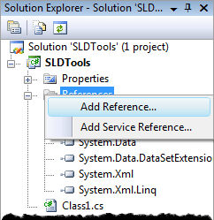
In the Solution Explorer (right side of screen) expand References.

Right click on References and select Add Reference.


Select the Browse tab on the Add Reference dialog box. Then browse to the install folder of AutoCAD (i.e. C:\Program Files\AutoCAD 2010\

From this location we will add two .dll files that will provide the AutoCAD API to develop custom apps in the .net environment. The two files are:

acdbmgd.dll
acmgd.dll

You can select and load both files at the same time. You should now see these added in your References list.

One more step before we can create a custom AutoCAD app! Highlight both of the newly added references and below the Solution Explorer in the Properties pane set Copy Local to False.


This is the basic setup for a new custom AutoCAD app. Here are two excellent resources to find more detailed information and sample code:

2. Through The Interface

In my next post we will develop a layer creation app.


Wednesday, September 15, 2010

Streamlined Method for Modifying an Enterprise CUI File

In a previoust post we talked briefly about CUI files. There are 2 primary CUI files used by an AutoCAD user profile: Main and Enterprise. By default the enterprise CUI file is read only. This makes it an excellent option for placing your custom network content in. The main CUI file can be on each user's local C:\ drive. This allows the users to modify their base AutoCAD environment to their preference without inadvertently modifying the shared network CUI file. The .arg file that we created in this earlier post is where the paths to each CUI file are defined.

With a production environment any changes made to the network CUI will be visible to all users the next time they load AutoCAD. So when we want to make a change to the network CUI we probably want to test it in our test environment and then here is a streamlined method to modify the live network CUI file:

1. Make a copy of the production .arg file that all of your designers are using to your local machine (or your test environment).

2. Rename the .arg file with some sort of "admin" tag.

3. Switch the path definitions for the Main CUI and the Enterprise CUI.

production .arg file:


admin .arg file:


This will create a user profile where the acad.cui file on your C:\ drive will be loaded as the enterprise (read only) CUI and the shared network CUI file will load as your main CUI which you can now edit. Just be careful since this is a live shared file. Also be careful for savvy users who get clever (or read this post!) and switch these path definitions to modify the shared network CUI file.

Safety note: Always keep a backup of the current production CUI file. This way if it is modified by a user you can replace it or if you make a mistake while editing the live file you can quickly restore the working file.

You can further streamline this environment by creating 3 desktop shortcuts (on your machine only) and changing the target (profile parameter):

1. (Production) Target = "C:\Program Files\AutoCAD 2010\acad.exe" /p "X:\SLD\Profiles\SLD.arg"

2. (Development) Target = "C:\Program Files\AutoCAD 2010\acad.exe" /p "X:\SLD_dev\Profiles\SLD_dev.arg"

3. (Admin) Target ="C:\Program Files\AutoCAD 2010\acad.exe" /p "X:\SLD_dev\Profiles\SLD_Admin.arg"

This makes each profile accessible quickly depending on the situation. You can now add a UI to a custom (or standard) command and have it available instantly to your designers without having to load anything on their machines.